How-To Guides and Videos
- ATTACHING THE POWERLITE INSIDE AND OUTSIDE THE MOUTH
The PowerLite has a battery pack which can be damaged if it is attached to an area on the speculum that can elicit a sharp blow to the battery pack. This can occur if a horse begins to shake his head violently when the speculum is opened. For this reason it is important to attach the PowerLite to an area that is not going to produce a hard blow to the battery case. Desirable places to attach the carabiner are as follows:
- Loosen one of the loops of the rope of the cleat on the PowerFloat dental halter. Attach a large key ring or snap ring to the rope at the front of the cleat. Attach the PowerLite carabiner to the ring on the cleat. This position is very good because it is easily accessible, it is out of the way of the work area, and it does not move if a horse begins to violently shake its head when the speculum is opened.
- Attach the carabiner of the PowerLite to the buckle of the nose band of the speculum. This position is safer than on the side straps that are connected to the metal of the speculum. The nose band is not near enough to any metal on the speculum that could cause impact to the battery pack.
- Attach the carabiner of the PowerLite to the upper part of the head stall straps so that the battery pack is well above the level of the metal on the side of the speculum. Do not attach the carabiner and battery pack to the side straps that are in close proximity to the steel on the side of the speculum. Head shaking can cause the battery pack to hit the steel hard enough to crack the batteries or battery pack.
- The LED and its magnetic case should be placed on the under side of the upper incisor plate of the speculum for optimal lighting of the mouth. The light case can be moved from side to side or just slightly swiveled from a central position to shine first on one side of the mouth then the other. It can be removed and attached to the battery pack area if room is needed to reach into the mouth between visual exams. A large washer attached to the carabiner is a good source of metal to attach the light to when doing hand examinations of the mouth
- INSTALLING DIASTEMA BURRS
- To install a diastema burr, first remove the grinding wheel from the PowerFloat (see instructions for removing a grinding wheel).
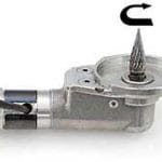
- Thread the diastema burr into the grinding head and turn it clockwise until finger-tight (Fig. 2). The diastema burr is now ready for operation
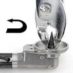
- To remove the diastema burr, lock the drive shaft (Fig. 1). Unscrew the diastema by turning it counter-clockwise (Fig. 3).
Note: It may be necessary to use a pair of pliers (pictured in Fig. 3) to grasp the burr at its base in order to loosen it, since burrs may become tighter after operation with PowerFloat models.

Fig. 1 Fig. 2 Fig. 3 - CHANGING THE SOLID GRINDING WHEEL
- Rotate the black metal ring cover to expose the opening in the housing shaft.
- Insert a small hex key (included with the new grinding wheel) or nail to lock the driveshaft. Note: Do not use a hypodermic needle to lock the drive shaft.
- Use the large hex key (included with the new grinding wheel) to loosen the screw in the center of the solid grinding wheel by turning it counter clockwise.
- Unscrew and remove the used grinding wheel.
- Put the new grinding wheel into place.
- Thread the new screw in the center of the grinding wheel into place turning clockwise until finger tight. Use the large hex key to tighten.
- Remove the small hex key from the housing shaft and rotate the metal cover back over the opening to keep it clear of debris.
- CHANGING THE CHAMFER BURRS
- Rotate the black metal ring cover to expose the opening in the housing shaft.
- Insert a small hex key (included with the new burr) or nail to lock the driveshaft. Note: Do not use a hypodermic needle to lock the drive shaft.
- Use the large hex key (included with the new burr) to loosen the screw in the center of the chamfer burr by turning it counter clockwise.
- Unscrew and remove the used chamfer burr.
- Put the new chamfer burr into place.
- Thread the new screw in the center of the chamfer burr into place turning clockwise until finger tight. Use the large hex key to tighten.
- Remove the small hex key from the housing shaft and rotate the metal cover back over the opening to keep it clear of debris.
- CHANGING THE DIAMOND GRINDING WHEEL
- Rotate the black metal ring cover to expose the opening in the housing shaft.
- Insert a small Allen key (included with the new grinding wheel) or nail to lock the driveshaft. Note: Do not use a hypodermic needle to lock the drive shaft as it can snap and break off.
- Insert the grinding wheel removal tool around the grinding wheel fitting it between the wheel and the guard on the right angle shaft. Rotate the grinding wheel counter clockwise to loosen. Alternately a very small sized vice-grip plier can be used to grasp the top of the grinding wheel to loosen.
- Unscrew and remove the used grinding wheel.
- Put the new grinding wheel into place. You will need to use a washer (included with the new grinding wheel) on the newer PowerFloat attachments in order to ensure the diamond grinding wheel surface is above the edge of the guard. On older models you may not require the washer.
- Thread the new grinding wheel into place turning clockwise until finger tight.
- Remove the Allen key from the housing shaft and rotate the metal cover back over the opening to keep it clear of debris.